Call / WhatsApp
+918282829795
uploads/2024/10/22//BoltSafe Network with PDI-NT.webp

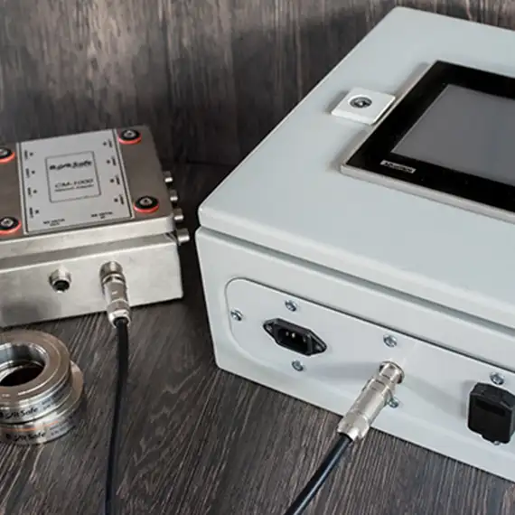
The network with the PDI-NT (Power Data Interface New Technology) readout system includes a PDI-NT box and one or more CM-1000 boxes, allowing continuous visualization of bolt load data from CMS sensors. Unlike the standard PDI box, the PDI-NT features an integrated display, eliminating the need for a PC. It also offers various analog output signals (4-20 mA or 0-10 Vdc), can generate alarms for high or low bolt loads, and trends bolt load data over a specified period. Additionally, it allows for the integration of BoltSafe load cells with other platforms. The CM-1000 Network box connects individual BoltSafe CMS load cells, with the ability to form a network of multiple CM-1000 boxes. This system is designed to withstand harsh environments and minimize electromagnetic interference (EMC noise).

Specifications

Connection capacity 8 BoltSafe CMS sensors
Temperature range -25°C to +80°C
Sealing IP66
Dimensions box 150x150x88 mm
Dimensions incl. connectors 162x174x88 mm
Material Stainless steel 1.4301 (AISI 304)
Weight 1,65 kg
CE-approval Tested to comply with: Emission EN 50081-1, EN 55022B Immunity, EN 61000-6-2, EN 61000-4-2, EN 61000-4-3, EN 61000-4-4, EN 61000-4-5, EN 61000-4-6, ENV 50204

 

How the Network with PDI Works

The network with PDI (Power Data Interface) consists of a PDI box and one or more CM-1000 boxes, allowing for continuous visualization of bolt load data. The PDI box connects the BoltSafe network to a PC or laptop running the BS-2000 software. Each CM-1000 box can accommodate up to eight BoltSafe CMS load cells, and multiple CM-1000 boxes—up to 32—can link to a single PDI box, enabling comprehensive monitoring. This system is built to withstand harsh environments and protect against electromagnetic interference (EMC noise).

Using the Network with PDI

Continuous bolt load data is analyzed using the “BS-2000 Network Monitoring Server” software. Installation is straightforward, with plug-and-play network and power cables. The PDI box connects to the PC or laptop via a standard USB cable. The CM-1000 box processes bolt load data locally, converting sensor values and storing user-defined tags and alarm settings. This decentralization enhances data polling speed, allowing updates from the BoltSafe load sensors every one to three seconds, even in extensive networks. During installation, the BS-2000 software automatically assigns node numbers to each connected unit, eliminating the need for additional settings. The CM-1000 box includes short circuit protection for each load cell, ensuring that the failure of one component does not disrupt the entire network. It also features connectors for easy attachment of the BoltSafe CMS load cells.

Variations of the Network with PDI

Users can set up a single PDI box and a CM-1000 network box to connect up to eight bolt load sensors and a PC. Alternatively, multiple CM-1000 boxes can be linked to one PDI, supporting up to 256 load cells. Typically, the PDI and network boxes are installed in a fixed location. However, for those needing flexibility, a portable system housed in a protective case is available as an optional feature. This setup is ideal for temporary measurements at different locations and can even be rented. Another optional feature includes a 4G module, allowing remote data access from any internet-connected PC.


Enquire Now


People Also Ask

The theory behind a load cell’s operation is based on measuring the deformation of a material under load. When a force is applied, it causes the load cell’s sensing element (usually a metal structure) to deform. Strain gauges attached to the structure detect this deformation by measuring changes in electrical resistance. The change in resistance is proportional to the applied force, allowing the load to be quantified as an electrical signal.

A load cell interface is the system or device that connects the load cell to a signal processing unit or display. The interface receives the electrical signal (from the strain gauges inside the load cell), amplifies it, and converts it into a readable format (such as kilograms, pounds, or newtons) for the user. Common interfaces include signal conditioners, transmitters, or digital indicators.

Connect the load cell to a signal conditioner or display unit. Apply a force to the load cell (e.g., by placing an object or weight on it). The load cell sends an electrical signal corresponding to the applied force. The signal is processed by the signal conditioner and displayed as a force value (in units like kg, lb, or N) on a digital display or readout device.

Measure the applied torque using a torque wrench or torque controller. Convert the measured torque into a bolt load using a formula that accounts for the torque coefficient (K) and the bolt’s diameter (D). A load cell can also be used to directly measure the bolt load during tightening, providing a more accurate measurement of the bolt’s tension.